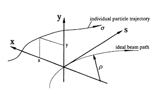
Circular coordinate system [1]
\begin{equation} \vec{R} ~=~ r \vec{x} + y \vec{z}, \end{equation}
where\begin{equation} r ~=~ \rho + x. \end{equation}
These coordinates represent deviations with respect to the ideal design orbit, we assume these deviations to be small; in reality $x$ is in the of order mm. We use the positions $x$ and $y$, and their slopes $x' = \frac{dx}{ds}$ and $y' = \frac{dy}{ds}$.
Circular coordinate system [2]
References
[1] R. Appleby. Beam Dynamics. Cockcroft Lectures 2011
[2] H. Weidemann. Particle Accelerator Physics I: Basic Principles and Linear Beam
Dynamics. Springer, 1999


No comments:
Post a Comment